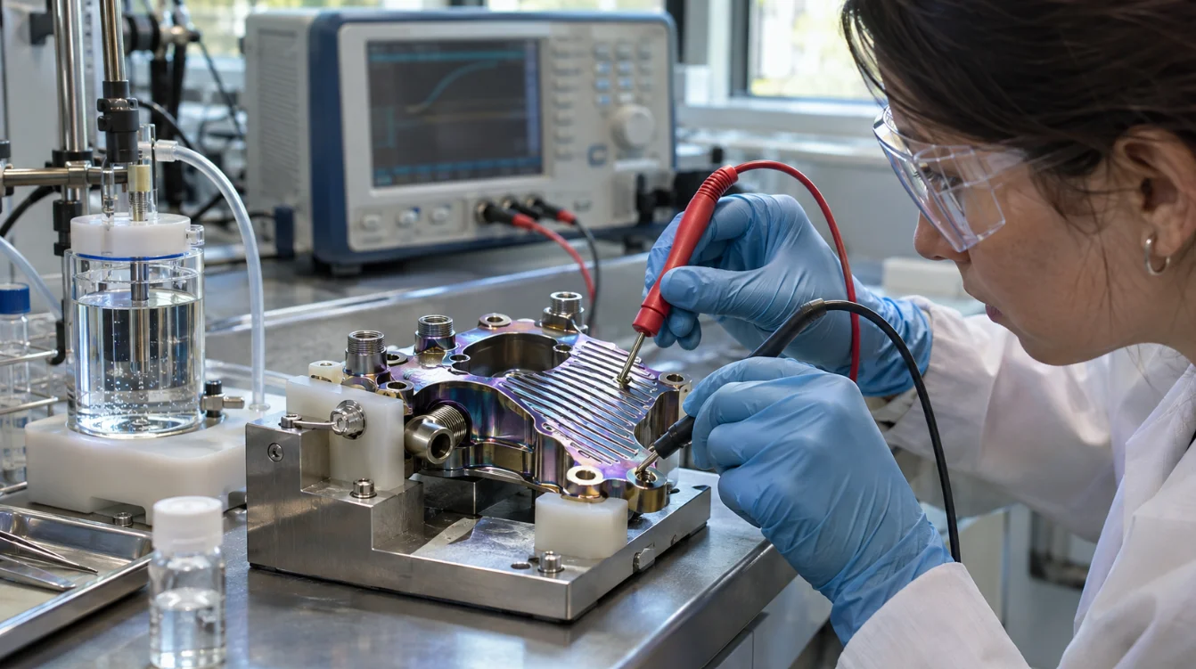
ALD coating continuity testing checks whether a thin film protects the surfaces that matter under the component’s actual operating conditions. Atomic Layer Deposition can produce highly conformal films, but conformality alone doesn’t prove that a barrier is continuous, defect-free, or durable on a finished part. Engineers need to match the verification method to the substrate, geometry, coating function, and expected exposure.
At VaporPulse Technologies, we develop custom ALD processes for complex geometries and non-standard substrates. A useful qualification plan starts by defining what failure the coating must prevent, then tests for that failure on a representative component or sample.
What does coating continuity mean?
A continuous barrier separates the substrate from the environment across the surfaces that require protection. A pinhole, uncovered patch, crack, or poorly coated edge can create a path for moisture, chemicals, or electrical current to reach the underlying material.
ALD grows films through repeated, self-limiting surface reactions. When the chemistry and process conditions suit the substrate, vapor-phase reactants can reach recessed surfaces and other features that line-of-sight methods may struggle to coat. But the result still depends on the part’s surface condition and the process. Contamination, particles, roughness, delayed film nucleation, or insufficient reactant exposure can leave weak spots.
The word “conformal” describes how a coating follows a shape. It doesn’t guarantee that every location has the same thickness or that the film blocks every relevant pathway. Even a film that looks uniform under a microscope may fail an electrical or chemical test.
Why doesn’t thickness prove the barrier works?
Thickness is one film property. Barrier performance also depends on film composition, structure, adhesion, defects, and stability in the service environment.
For example, a thickness measurement on an accessible surface doesn’t show whether reactants reached the bottom of a deep channel. A sample may meet its nominal thickness target but still have incomplete coverage where the substrate’s surface chemistry delayed film growth. And a coating that starts out continuous may crack during assembly or lose performance after heat, bending, abrasion, or chemical exposure.
A 2025 study of ALD alumina barriers used cyclic voltammetry and electrochemical impedance spectroscopy to examine insulation and stability in a specific electrochemical system. The researchers found that the thickness needed for stable performance in their tests exceeded the minimum needed to form a continuous film. That result underscores why acceptance should be based on the required function, not a thickness number alone. The study’s results apply to its tested materials and conditions, so they don’t establish a universal thickness rule for other components. (Read the study on ALD alumina barrier stability.)
Choose a test that matches the coating’s job
Start with the failure the coating needs to prevent. The test should reproduce the relevant pathway and operating conditions as closely as practical.
For an electrically insulating film on a conductive part, leakage-current or dielectric testing may reveal a defect that exposes the substrate. Electrochemical impedance spectroscopy or cyclic voltammetry can be useful for some coated-electrode applications, where the electrolyte and electrical response match the real use case.
For chemical or corrosion protection, expose the coated part or representative sample to the actual fluid, vapor, concentration, temperature, and duration. Then inspect for corrosion, chemical attack, or changes in the component’s performance. A test using a different chemical or a much shorter exposure can miss the failure mode that matters in service.
For moisture barriers, measure moisture ingress or the downstream performance of the protected device under controlled humidity conditions. For optical or dimensional applications, check the relevant optical response or critical dimensions before and after deposition and exposure.
Microscopy and cross-section analysis can show local film thickness, structure, and coverage. They’re valuable when investigating a suspected defect, but they inspect a limited area. A clean image from one location doesn’t establish that every hidden surface on a complex part has the same condition.
Test representative geometry, not just a flat coupon
A flat witness coupon can provide useful information about film growth or chemistry. It may not represent a finished component with blind holes, long channels, sharp transitions, pores, threads, or assembled materials.
Reactants need enough time and access to travel into recessed features, react at the surface, and clear during purging. If that exposure is insufficient, the film near an opening may differ from the film deeper inside. The part’s orientation and how it sits in the chamber can also affect exposure.
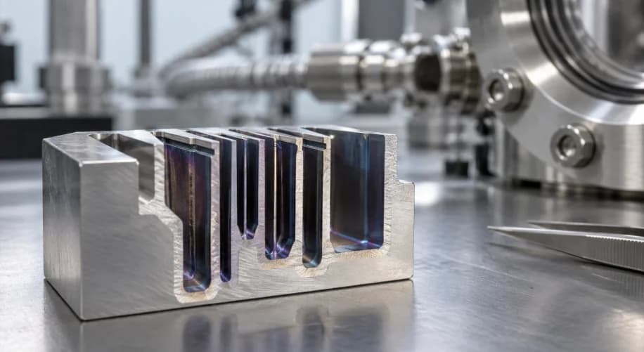
For that reason, pair witness samples with a representative component or a deliberately designed geometry sample when internal coverage matters. If destructive inspection is available, a cross-section through the feature of concern can show local coverage. VaporPulse’s complex geometry coating services address parts with internal features and high-aspect-ratio structures. Our article on coating the inside of stainless steel tubes and small bores explains why geometry and precursor exposure matter for those parts.

Build acceptance criteria before coating
A useful qualification plan spells out the decision before testing begins. Record the substrate and surface condition, identify which surfaces need protection, and define the exposure the coating must withstand. Include any thermal cycling, mechanical loading, cleaning, or assembly steps that could change the film.
Then identify the measurement that will determine pass or fail. That could be a maximum leakage current, a corrosion limit, a specified change in component performance, or a dimensional tolerance. Where practical, compare coated samples with uncoated controls. A baseline helps distinguish coating-related effects from changes caused by the substrate or test setup.
The sampling plan matters too. Agree on which locations to inspect, whether testing will use coupons or full parts, and whether any measurement requires destructive sectioning. For internal features, state where coverage must be verified rather than relying on a measurement from an easily reached outer surface.
What can engineers conclude from a continuity test?
A test supports a conclusion about the locations, samples, and conditions it covers. It can show that a process met a defined requirement under a particular test. It cannot establish that a coating is universally pinhole-free or that the same result will hold for every geometry, material, or service environment.
That distinction helps engineers choose the next step. If a barrier test finds a failure, investigate the location and failure mechanism before changing the film thickness or chemistry. The cause could involve nucleation, surface contamination, feature access, adhesion, edge coverage, or damage after deposition. Different causes call for different process changes.
VaporPulse develops ALD processes for delicate substrates, complex parts, prototypes, and low-volume projects. If you’re planning ALD coating continuity testing, share the part drawing, substrate details, critical surfaces, operating environment, and the failure the coating must prevent. Contact our team to discuss a practical way to evaluate the coating on representative parts.
Our Other Blogs
november 2, 2026
What Controls ALD Coating Uniformity in High-Aspect-Ratio Features?

october 17, 2026
Thermal ALD vs Plasma ALD: How Does the Process Differ?

october 6, 2026
Can ALD Protect Components From Chemical Exposure Without Changing Critical Dimensions?

september 14, 2026
How Do You Protect Polymer Components Without Plasma Damage?

september 1, 2026
How to Coat the Inside of Stainless Steel Tubes and Small Bores
Subscribe to Our Newsletter
Stay up to date with our latest news, blog posts, and exclusive updates delivered right to your inbox.